- Crack Width Calculation As Per Aci 318 14 Online
- Crack Width Calculation As Per Aci 318 14 Pdf
- Crack Width Calculation As Per Aci 318 14 Free

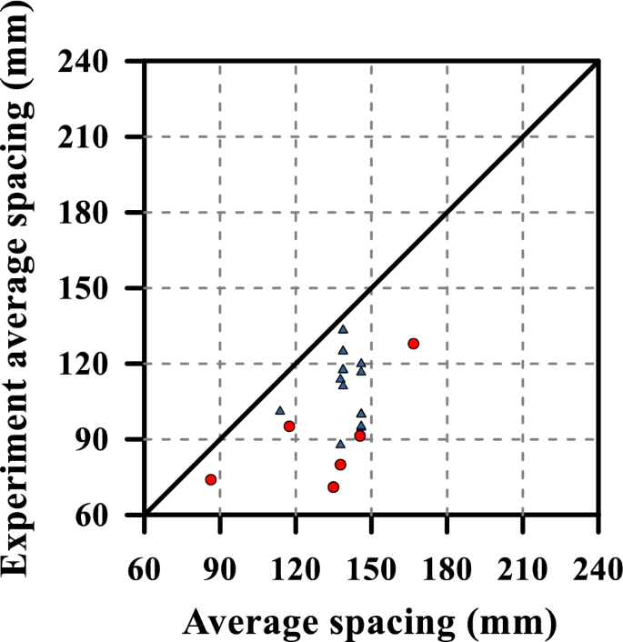
Crack width calculation is one of the serviceability require. Strong influence on the crack spacing. Gilbert and Nejadi 14. Corresponding to a limiting crack width of 0.41 mm. Coefficient of friction μ per Building Code Requirements for Structural Concrete (ACI 318-05) and Commentary (ACI 318R-05).2 PCI’s basis for the use of μ e was justified by research and publications by A. Fattah Shaikh3 and relationships presented by Charles H. Raths.4 These works followed Allan H. Mattock’s earlier research and articles.
FOR WATER TIGHT STRUCTURES
Crack width is a complex and tough topic. Most people still use 20 years old method defined in ACI 318-95. The situation becomes more complex if axial tension force and moment is combined to calculate crack width. One of the examples is large water tanks above ground. This tutorial aims at explaining details and methods in different ACI documents. Latest method defined in ACI 350-06 should be used. Given the variability and non-linear behaviour in long-term deflection and crack widths, it is NOT NEEDED to go for detailed sophisticated calculations for these effects. You can imagine this as calculating something non-linear (crack widths or long-term deflection) from linear-elastic analysis. You have to have some approximations for that. No matter how detailed are your calculations, you still can’t predict for certain the long-term deflection and crack widths.
Three ACI documents for crack width; ACI 224R-01, ACI 350-01 & ACI 350-06
1. ACI 224R-01
Some notes:-
- Table 4.1 is based on Nawy findings.
- The table is just a general guide line.
- The table gives w=0.004″ or 0.10mm for water retaining structures.
- It is expected that portion of cracks will exceed these values by a significant amount.
- No relationship between level of cracking & corrosion in long-term.
- More cover can be used even if it yields larger crack width, against corrosion.
- ACI methods deal only with conventional concrete for crack width.
- Crack width is directly proportional to dia of bar & fs and inversely to area of steel.
- Three reasons for limiting crack widths
1-Appearance
2-Corrosion
3-Water tightness
There are three methods mentioned in this document
A) ACI 318-95
Statistical method of Gergely & Lutz 1968
Covers up to 2.5″ only
z in any units
For two-way slabs see section 4.3 of ACI 224R-01
For shallow beams/thick one-way slabs: (w in inches)
Thick means L/D = 15-20
d used here will be distance to the center of bottom bar nearest to tension face.
ß=1.25 to 1.35 if cc≥1″
ACI 318-95 section 10.6 says use ß=1.20 & fs=0.6fy
ACI 340R has design aids for z
ACI 318-98 & earlier max z=175 kip/in for interior exposure based on 0.41mm probable crack width(0.016″)
ACI 318 max z=145 kip/in for exterior exposure based on 0.33mm probable crack width(0.013″)
B) ACI 318-99
No distinction for interior/exterior exposure
For beams & one-way slabs:
fs=0.6fy
Not for aggressive/water tight structures
C) EUROPEAN CODES
—————————————————————————————————————————
2. ACI 350-01
Same concept like ACI 224R-01
—————————————————————————————————————————
3. ACI 350-06
2 types of exposure:-
i)Normal
ii)Severe

can be taken = 25
where c is at service load
ß can be taken = 1.20 for h≥16″
& 1.35 for h<16″
where appearance is of concern & cover exceeds 3″, also check equation 10-7
Exposure defined as
Previous codes (ACI 350-01) puts following limits on z:
Normal exposure: z=115 kip/in (w=0.010″ or 0.254mm)
Severe exposure: z= 95 kip/in (w=0.009″ or 0.229mm)
—————————————————————————————————————————
EXAMPLE WITH AXIAL TENSILE LOAD AND MOMENT
- For detailed calculations, find the N.A. depth but use ԑ at service loads. Strain diagram will be different from the one shown in figure above if axial load is included.
- Assume no strength from concrete due to axial tension load.
- Assume tension force acting at steel reinforcement level.
- Assume all the moment is resisted by top and bottom steel only.
- Tension at top steel; T1 = A’s / (A’s+As+As1+As1) x Total Tension Force
- Tension at bottom steel;T2 = As / (A’s+As+As1+As1) x Total Tension Force
- Tension at right steel; T3 = As1/ (A’s+As+As1+As1) x Total Tension Force
- Tension at left steel; T4 = As1/ (A’s+As+As1+As1 )x Total Tension Force
- Taking moment about top steel:
M=Asfs(d-d’)+T2(d-d’)+0.5T3(h/4)+0.5T4(h/4)
T3=T4 so
M=Asfs(d-d’)+T2(d-d’)+T3(h/4)
(where T is total axial tension force)

From here calculate fs and compare with fsmax of ACI 350-06.
Eurocode 2 part 1-1: Design of concrete structures 7.3 Crack control
The crack width, wk, may be calculated as follows:
| wk = sr,max⋅(εsm - εcm) | (7.8) |
where:
- sr,max
- is the maximum crack spacing
- εsm
- is the mean strain in the reinforcement under the relevant combination of loads, including the effect of imposed deformations and taking into account the effects of tension stiffening
- εcm
- is the mean strain in the concrete between cracks.
| (7.9) |
where:
see application for a rectangular section or application for a T-section
with
- Ecm
- the secant modulus of elasticity of concrete
fct,eff = fctm or lower, (fctm(t)), if cracking is expected earlier than 28 days
Crack Width Calculation As Per Aci 318 14 Online
| = (As + ξ1⋅A'p)/Ac,eff | (7.10) |
with
Crack Width Calculation As Per Aci 318 14 Pdf
| ξ1 = | (7.5) |
with
- ξ
- the ratio of bond strength of prestressing and reinforcing steel, according to Table 6.2
- ΦS
- the largest bar diameter of the reinforcing steel
- ΦP
- the diameter or equivalent diameter of prestressing steel:
Φp = 1,6⋅√AP for bundles, where AP is the area of a prestressing steel,
Φp = 1,75⋅Φwire for single 7 wire strands,
Φp = 1,20⋅Φwire for single 3 wire strands, where Φwire is the wire diameter.
kt = 0,6 for short term loading,
kt = 0,4 for long term loading.
• Where the bonded reinforcenlent is fixed at reasonably close centres within the tension zone (spacing ≤ 5(c + Φ/2), cf. Figure 7.2), the maximum crack spacing sr,max may be calculated as follows:
| sr,max = k3c + k1k2k4Φ / ρp,eff | (7.11) |
where:
Crack Width Calculation As Per Aci 318 14 Free
k1 = 0,8 for high bond bars,
k1 = 1,6 for bars with an effectively plain surface (e.g. prestressing tendons).
k2 = 0,5 for bending,
k2 = 1,0 for pure tension.
Intermediate values of k2 should be used for cases of eccentric tension or for local areas:
| k2 = (ε1 + ε2)/(2ε1) | (7.13) |
where ε1 is the greater and ε2 is the lesser tensile strain at the boundaries of the section considered, assessed on the basis of a cracked section.
• Where the spacing of the bonded reinforcement exceeds 5(c + Φ/2) (cf. Figure 7.2), or where there is no bonded reinforcement within the tension zone, the maximum crack spacing sr,max may be calculated as follows:
| sr,max = 1,3(h - x) | (7.14) |
where:
- h
- is the overall depth of the section (see Figure 7.1)
- x
- is the neutral axis depth of the section (see Figure 7.1).
This application calculates the crack width wk from your inputs. Intermediate results will also be given.
First, change the following option if necessary: